

Outdoor Monitors Temperature Control
Our outdoor monitors are equipped with an intelligent cooling control unit, which regulates the speed of the built-in fans depending on the current temperature, thus protecting the monitor from high heat loads.
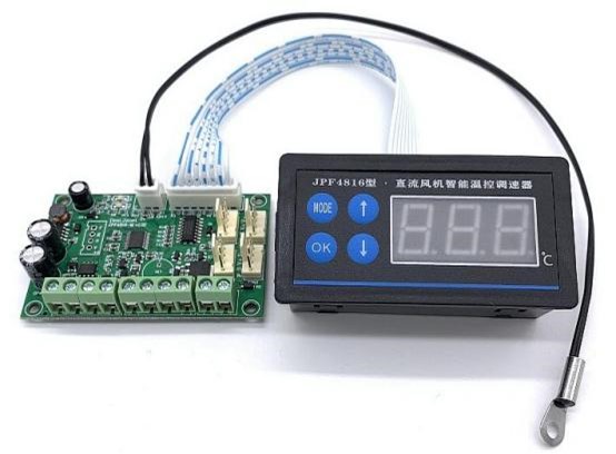
Operation overview:
ARM core is an industrial-grade technical solution using a single-chip microcomputer as the main control chip, with a temperature display frame, which can be directly embedded in the panel of various cabinets. The controller controls the fan speed through the detected temperature. The higher the temperature, the higher the speed.
When the temperature is lower than the starting temperature, the fan stops or maintains the minimum speed. When it is higher than the starting temperature, the fan runs at low speed. When the temperature is high, the fan runs at full speed, and when the temperature starts to drop, the fan speed will also automatically decrease to work in a cycle;
The speed controller supports communication via RS485 serial port. Through the serial port protocol, the fan speed can be controlled, and the parameters/status of the speed controller can be configured/queried. The serial port commands follow the modbus-rtu protocol, and the fan speed can be adjusted from 0-100%.
The speed controller supports communication via RS485 serial port. Through the serial port protocol, the fan speed can be controlled, and the parameters/status of the speed controller can be configured/queried. The serial port commands follow the modbus-rtu protocol, and the fan speed can be adjusted from 0-100%.
Product performance/technical parameters:
1. Industrial-grade solution, using ARM core series single-chip microcomputer as the main control chip, with stable performance.
2. Wide voltage design, 12V/24V/48V 4-wire PWM fan/motor direct access, maximum drive current 6A
3. With LED display, visually indicating the working status of the controller
4. Power supply anti-reverse connection protection design, reverse connection of the power supply will not burn the board.
5. The start and full-speed temperatures can be freely set, and two working modes are supported: minimum speed and stop fan
6. Supports fan fault detection and fan fault NPN signal output.
7. Standard modbus-rtu protocol, supports RS485 serial port to set various parameters and query fan status.
8. RS485 serial port TVS anti-surge design, serial port parameters default to 9600bps, 8, N, 1
9. Fan power management, 100% shutdown of all 4-wire fans.
10. PWM output frequency adjustable, amplitude 5V
11. Temperature measurement range: -10~99 ℃,
12. Temperature measurement accuracy: ±1°C
13. Working temperature range: -30~80℃
14. Support fan speed detection.
2. Wide voltage design, 12V/24V/48V 4-wire PWM fan/motor direct access, maximum drive current 6A
3. With LED display, visually indicating the working status of the controller
4. Power supply anti-reverse connection protection design, reverse connection of the power supply will not burn the board.
5. The start and full-speed temperatures can be freely set, and two working modes are supported: minimum speed and stop fan
6. Supports fan fault detection and fan fault NPN signal output.
7. Standard modbus-rtu protocol, supports RS485 serial port to set various parameters and query fan status.
8. RS485 serial port TVS anti-surge design, serial port parameters default to 9600bps, 8, N, 1
9. Fan power management, 100% shutdown of all 4-wire fans.
10. PWM output frequency adjustable, amplitude 5V
11. Temperature measurement range: -10~99 ℃,
12. Temperature measurement accuracy: ±1°C
13. Working temperature range: -30~80℃
14. Support fan speed detection.
Mounting size: 63mm*40mm.
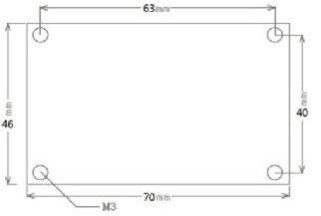
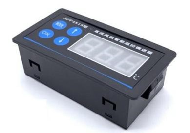
External Size: 79mm*42mm*26mm; Installation Size: 76mm*40mm
Interface Description
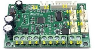
No. 1: Control power supply + pole interface
No. 2: Speed control power supply - pole interface
No. 3: RS485 serial port A / D+; No. 4 terminal: RS485 serial port B / D-
No. 5 terminal is connected to the fan power supply -, No. 6 terminal is connected to the fan power supply +, No. 7 terminal is connected to the fan speed signal, and No. 8 terminal is connected to the fan PWM control line.
*5~8 The numbers are mainly for the convenience of wiring the fan without plugs, and can be directly connected with the 4 pins of the 14th interface.
No. 9: fan fault indicator OC output port (NPN output interface) (* see the instructions at the end of the article)
No. 10: GND
No. 11: Display board port
No. 12: Temperature measurement port
No. 13: LED indicator light, POW is the power indicator light of the whole machine, PWM is the fan control indicator light.
14~17: 4 fan ports, standard KF2510-4P socket, (P=PWM, S=Sensor/FG, FV+, FV-)
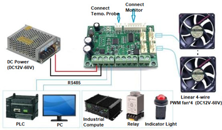
*Schematic diagram of full-function wiring: (Some functions cannot be used, just ignore the wiring The actual in use.)
*The voltage of the DC power supply must match the rated voltage of the connected fan, and the output current must be greater than the sum of the fan currents.
*Do not connect and disconnect the fan while the power is on.
No. 2: Speed control power supply - pole interface
No. 3: RS485 serial port A / D+; No. 4 terminal: RS485 serial port B / D-
No. 5 terminal is connected to the fan power supply -, No. 6 terminal is connected to the fan power supply +, No. 7 terminal is connected to the fan speed signal, and No. 8 terminal is connected to the fan PWM control line.
*5~8 The numbers are mainly for the convenience of wiring the fan without plugs, and can be directly connected with the 4 pins of the 14th interface.
No. 9: fan fault indicator OC output port (NPN output interface) (* see the instructions at the end of the article)
No. 10: GND
No. 11: Display board port
No. 12: Temperature measurement port
No. 13: LED indicator light, POW is the power indicator light of the whole machine, PWM is the fan control indicator light.
14~17: 4 fan ports, standard KF2510-4P socket, (P=PWM, S=Sensor/FG, FV+, FV-)
*Schematic diagram of full-function wiring: (Some functions cannot be used, just ignore the wiring The actual in use.)
*The voltage of the DC power supply must match the rated voltage of the connected fan, and the output current must be greater than the sum of the fan currents.
*Do not connect and disconnect the fan while the power is on.
Basic Instructions
5.1 Connect the wires according to the interface description
5.2 After the power supply is correct, the POW lamp on the motherboard will light up. At this time, the controller will start to sense the current temperature and adjust the fan speed according to the currently set temperature range.
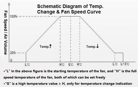
Take the factory default temperature range of the controller as an example. The default temperature range of the controller is L=30°C, H=50°C. When the current temperature is detected as greater than or equal to 30°C, the controller will adjust the fan speed in linear proportion. When the temperature rises, the fan speed will also increase. When the temperature is ≥50℃, the fan will switch to full speed. When the temperature drops to ≤27°C (L-3), the controller will keep the fan at minimum speed and/or turn off.
5.2 After the power supply is correct, the POW lamp on the motherboard will light up. At this time, the controller will start to sense the current temperature and adjust the fan speed according to the currently set temperature range.
Take the factory default temperature range of the controller as an example. The default temperature range of the controller is L=30°C, H=50°C. When the current temperature is detected as greater than or equal to 30°C, the controller will adjust the fan speed in linear proportion. When the temperature rises, the fan speed will also increase. When the temperature is ≥50℃, the fan will switch to full speed. When the temperature drops to ≤27°C (L-3), the controller will keep the fan at minimum speed and/or turn off.
Fan speed and temperature chart:
Guide to operating the digital panel:
The digital panel displays the current temperature in real time, and is operated with 4 buttons, through which all the parameters of the controller can be set.
In standby mode, press the "MODE" button to enter the configuration/switching parameter item, press the t button to set the value during configuration, and then press the "OK" button to confirm the setting.
In standby mode, press the "MODE" button to enter the configuration/switching parameter item, press the t button to set the value during configuration, and then press the "OK" button to confirm the setting.
*When setting parameters, each time you set a parameter (change the parameter value), you must press the "OK" button once to confirm, and then after setting the next item.
The parameter elements are as follows:
Take as an example the setting of the fan start and full speed temperature:
In standby mode, the panel displays the current temperature value, press the "MODE" button once, the digital tube displays "Lxx", "L" represents the starting temperature, and "xx" represents the current set temperature value;
Press the up and down buttons to adjust the parameter value. After the setting is completed, press the "OK" button to confirm and return to the standby interface.
In the standby mode, press the "MODE" button twice, the digital tube displays "Hxx", "H" represents the full-speed temperature, "xx" represents the current set temperature value, press the up and down buttons to adjust the parameter value, after the setting is completed, press the "OK" button to confirm.
After the setting is completed, the controller will automatically adjust the fan speed according to the newly set temperature parameters.
The setting of other parameters is similar to the above steps.
*The above parameters can also be configured/queried through the RS485 serial port, in addition to the buttons, the following can also be used to set.
In the standby mode, press the "MODE" button twice, the digital tube displays "Hxx", "H" represents the full-speed temperature, "xx" represents the current set temperature value, press the up and down buttons to adjust the parameter value, after the setting is completed, press the "OK" button to confirm.
After the setting is completed, the controller will automatically adjust the fan speed according to the newly set temperature parameters.
The setting of other parameters is similar to the above steps.
*The above parameters can also be configured/queried through the RS485 serial port, in addition to the buttons, the following can also be used to set.